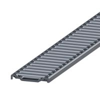
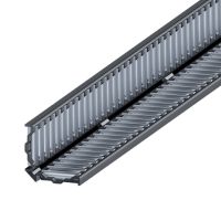
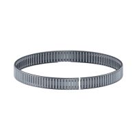
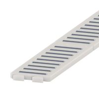
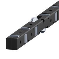
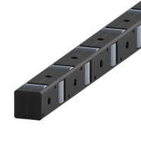
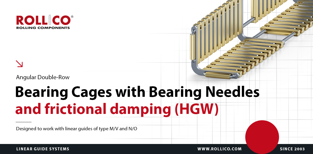
Bearing cages
The linear bearing cage is an essential component of a linear rolling bearing built with the use of linear guides. The main task of the bearing cage is to hold the rolling elements inside the bearing on the guide's raceways in the correct operating position.
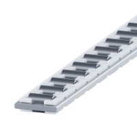
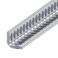
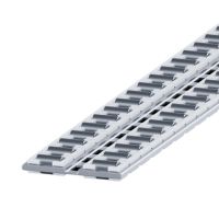
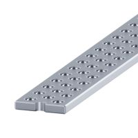
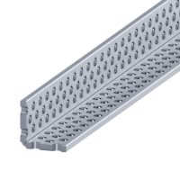
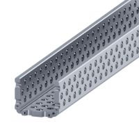
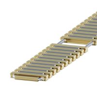
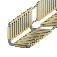
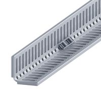
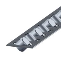
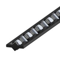
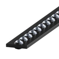
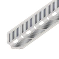
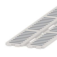
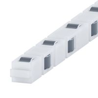
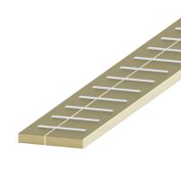
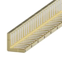
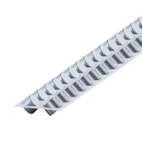
HGW
Technical drawing of HGW bearing cages
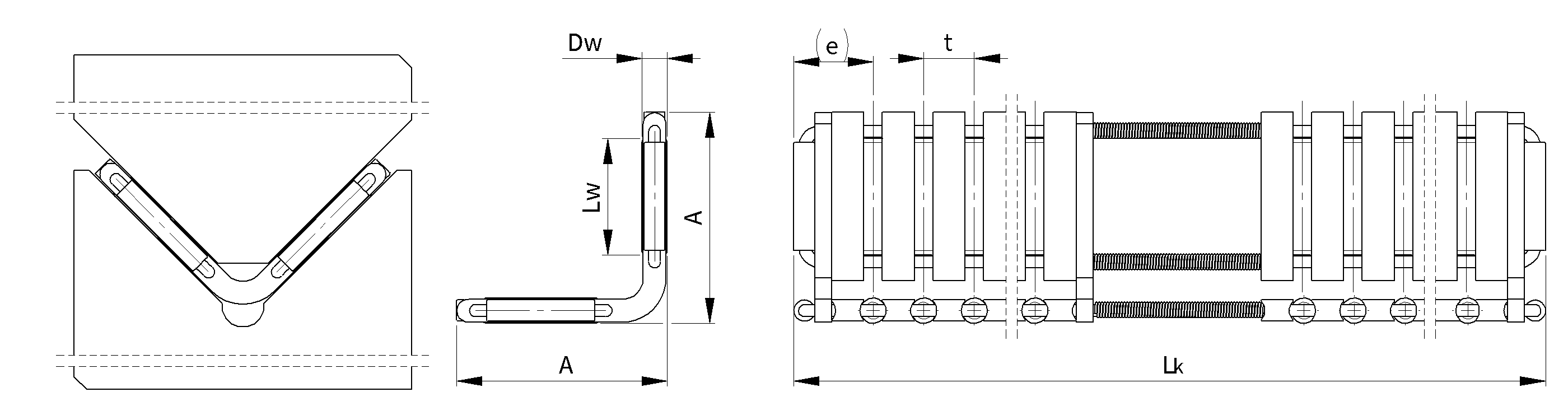
Dimension table of HGW bearing cages
|
Needle
diameter Ø |
Type/symbol
|
Dimensions
|
Load capacity *
|
Damping force
|
||||||
|---|---|---|---|---|---|---|---|---|---|---|
|
A
|
e
|
DW
|
LW
|
t
|
LK
max |
C
[N] |
CO
[N] |
RS**
[N] |
||
|
2
|
HGW 15
|
13.5
|
10
|
2
|
6.3
|
4.5
|
1 500
|
21 900
|
70 500
|
9
|
|
2.5
|
HGW 20
|
19.5
|
7.3
|
2.5
|
9.8
|
5
|
1 500
|
38 000
|
123 800
|
16
|
|
3
|
HGW 25
|
25
|
9.4
|
3
|
13.8
|
6
|
1 500
|
57 200
|
185 500
|
22
|
|
3.5
|
HGW 30
|
30.5
|
10.3
|
3.5
|
17.8
|
7
|
1 500
|
73 800
|
232 100
|
28
|
|
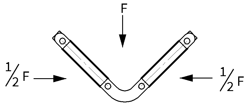
*) - Load capacity for the theoretical length of the cage of 100 mm with the thrust force "F" in accordance to the drawing. - Formula for calculation of the oscillations damping force for the effective length of a bearing cage |
||||||||||
Weight table of HGW bearing cages
| Table for weight values of bearing cages (for the length of Lk=1000 mm) [g] |
|
|
Type/symbol
|
Brass |
| HGW 15 | 265 |
| HGW 20 | 470 |
| HGW 25 | 760 |
| HGW 30 | 1150 |