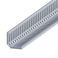
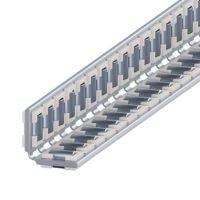
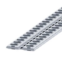
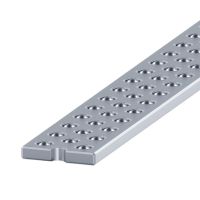
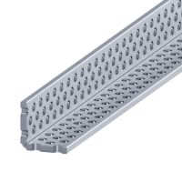
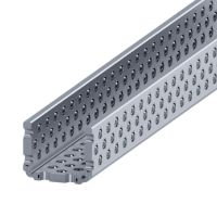
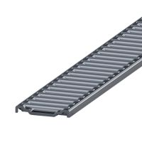
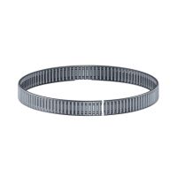
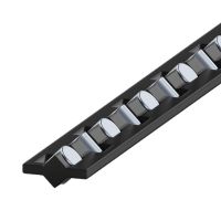
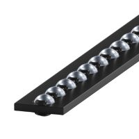
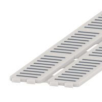
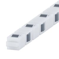
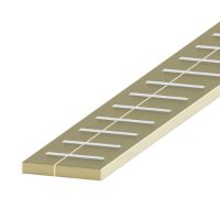
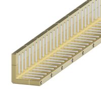
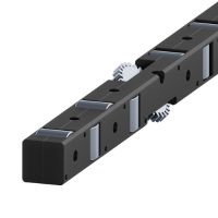
The linear bearing cage is an essential component of a linear rolling bearing built with the use of linear guides. The main task of the bearing cage is to hold the rolling elements inside the bearing on the guide's raceways in the correct operating position.
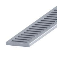
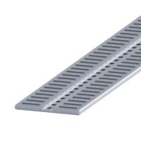
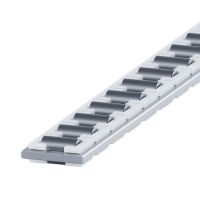
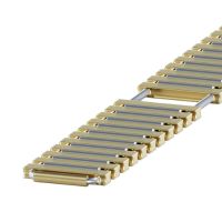
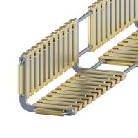
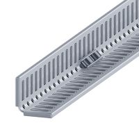
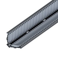
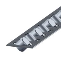
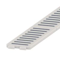
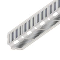
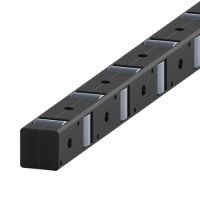
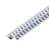
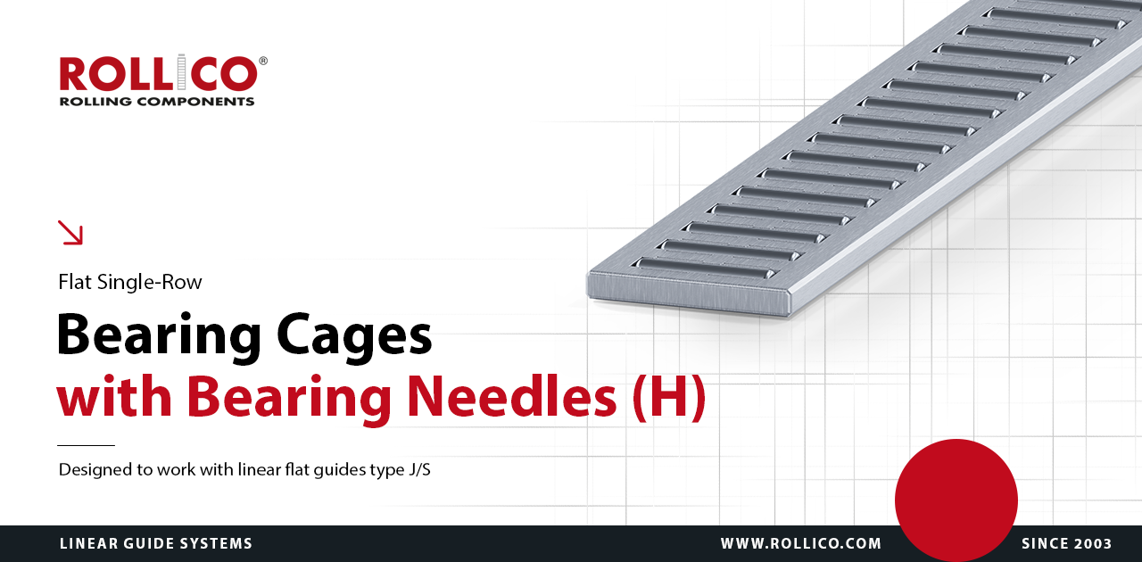
Flat single-row bearing cages with bearing needles
Manufactured from profiles of light metals - aluminium (Al), brass (Ms) or steel (F)
High precision and strength at low deadweight (aluminium)
Destined for heavy-duty working conditions at high loads and accelerations
Working temperature up to 150°C
Applicable to linear flat guides
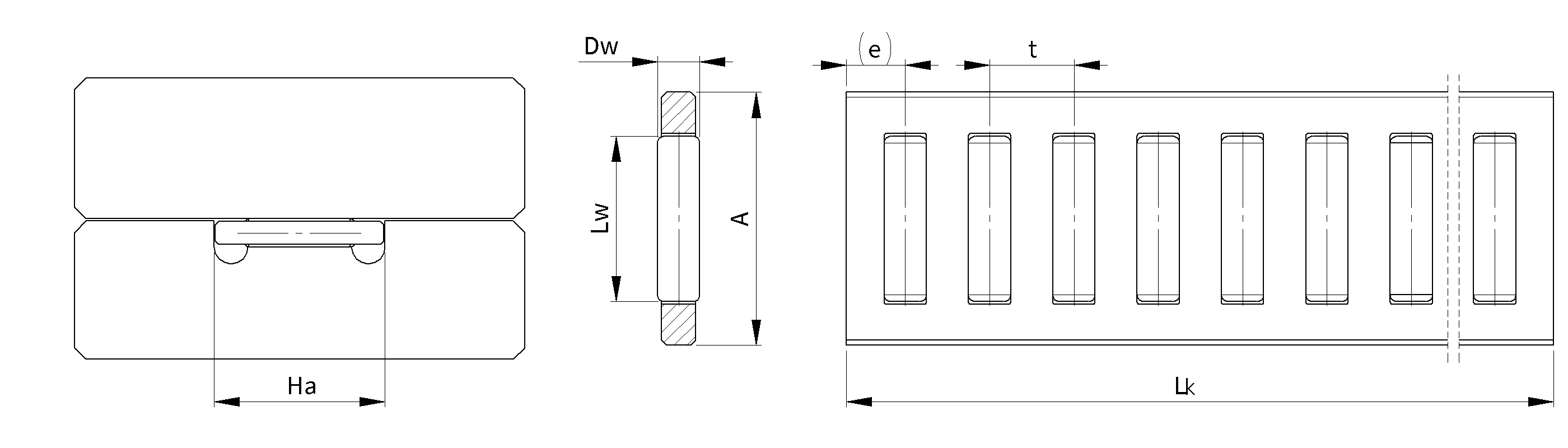
Technical drawing of H bearing cages
Dimension table of H bearing cages
Needle
diameter
Ø
Type
/symbol
Dimensions
Load capacity *
Functional
dimension
A
DW
LW
t
e
LK
max
C
[N]
CO
[N]
Ha
2
H 10
10
2
6.8
4.5
3.5
2 000
21 600
62 800
10.3+0.2
2.5
H 15
15
2.5
9.8
5
3.5
2 000
35 800
103 800
15.3+0.2
3
H 20
20
3
13.8
6
4.5
2 000
51 900
148 000
20.4+0.2
3.5
H 25
25
3.5
17.8
7
5
2 000
68 200
190 000
25.4+0.2
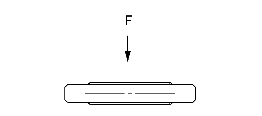
*) - Load capacity for the theoretical length of the cage of 100 mm with the thrust force "F" in accordance to the drawing.
- The load capacity is calculated for guides with hardness of 60 +/- 2 HRc oand surface roughness of Ra<0.4.
- Load capacity of bearing cages is calculated on the basis of number of bearing needles mounted in the cage
- Length tolerance LK +0/-t
Weight table of H bearing cages
Table for weight values of bearing cages Lk=1000 mm [g]
Type/symbol
Aluminium
Steel
Brass
H 10
>63
127
-
H 15
120
224
234
H 20
202
369
389
H 25
294
546
575
AlAluminum
MsBrass
FSteel
Precision
Sorting tolerance
up to 0.5 µm
Quality
Quality Management System
compliant with ISO 9001:2015
Experience
Over 20 years of expertise
in linear technology.
Customization
We manufacture components
tailored to individual requirements